FDM -design guide
There is no doubt that every manufacture has their own limitation. The following would introduce some design skill and potential method to help build 3D part.
In the following introduction, we would use 3D printing software Ultimaker Cura and EBU 3D printing to show how to use.
 Obviously, we can find many different kinds of 3D printing software, MakerBot Print,Repetier,Simplify3D,slic3r
For FDM 3D printing, you can choice one by yourselves.
Obviously, we can find many different kinds of 3D printing software, MakerBot Print,Repetier,Simplify3D,slic3r
For FDM 3D printing, you can choice one by yourselves.
1 Overhangs
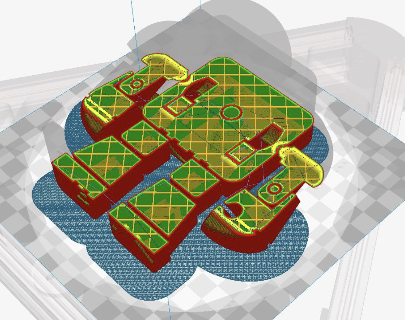
I use the test support model to test the performance of 3D printer.


There is no doubt that support in 3D printer model will influence the detail of the surface and we need tool to polish it(sandpaper, knife,Water outlet pliers, file ,etc)
This model can make sure which angle need to support, and the right picture show the test result of the machine performance in support. If the degree bigger than 45, we'd better add support. Of course different machine has different parameter ,the above just for reference.
2 Bridge

If the bridge is too bigger ,the bottom of the model would drop down because of gravity, so we need to control the distance . If the distance have to be big ,we need to add support to make sure the bottom.
3 Connection
If we want to make rotation part together, we need to make sure the gap between hole and axis, in this case we need to leave about 1mm(this model is from thingiverse)
4 Wall thickness
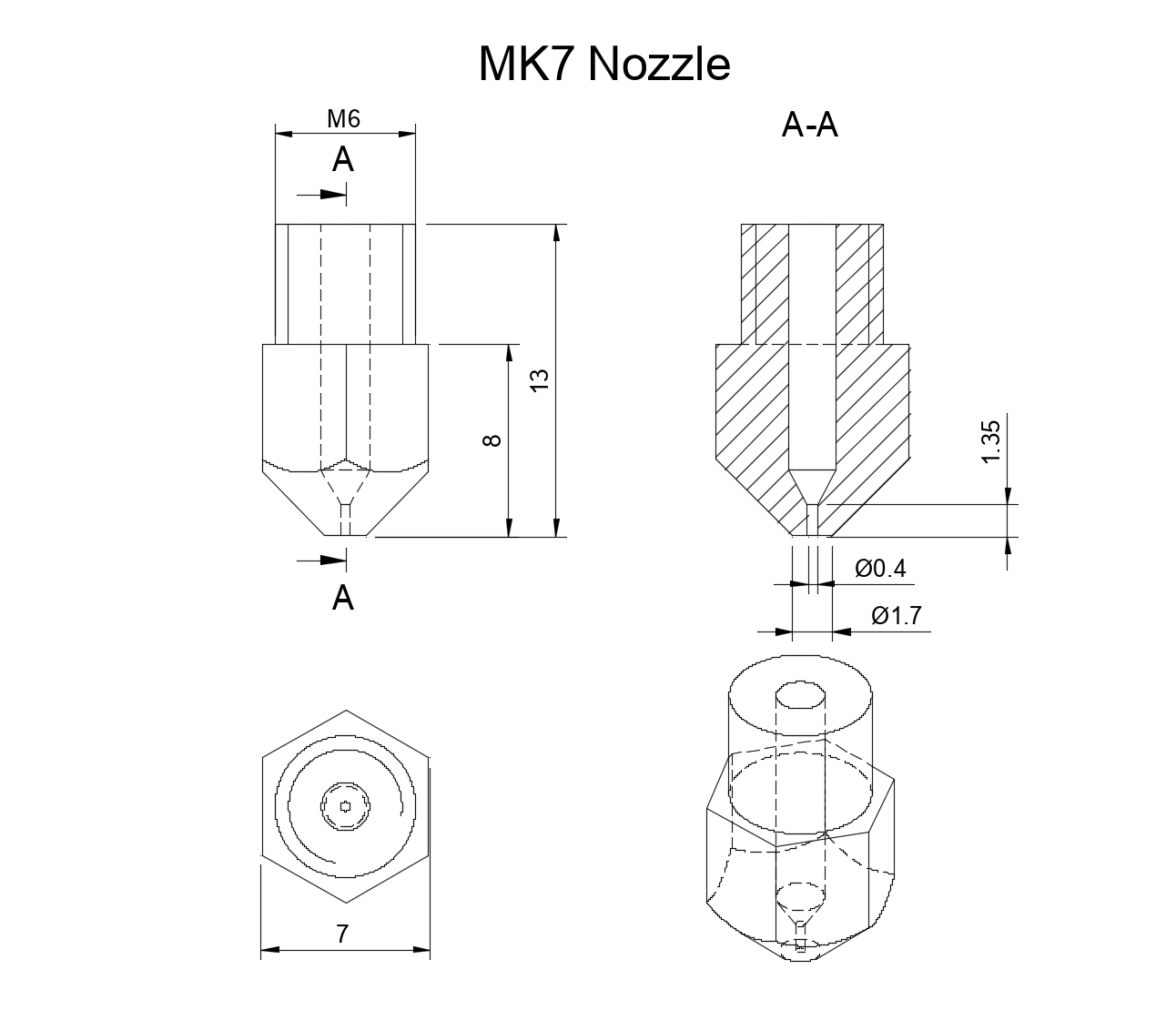
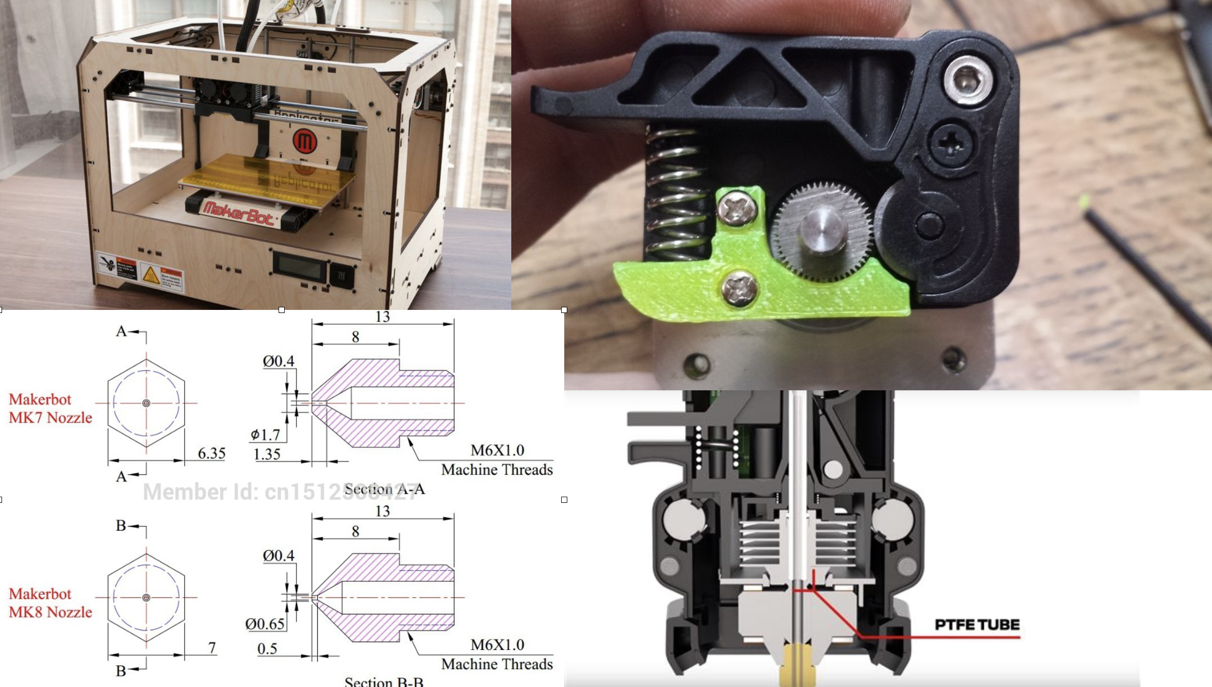
Normally we would use MK7 nozzle, and the output hole is 0.4mm.
 Reference the attach 3D model
To make sure the strength, we need at least 2 layers(0.4*2=0.8mm)for thin wall, normally we would choice 3 layers(1.2mm).
5 Vertical pole
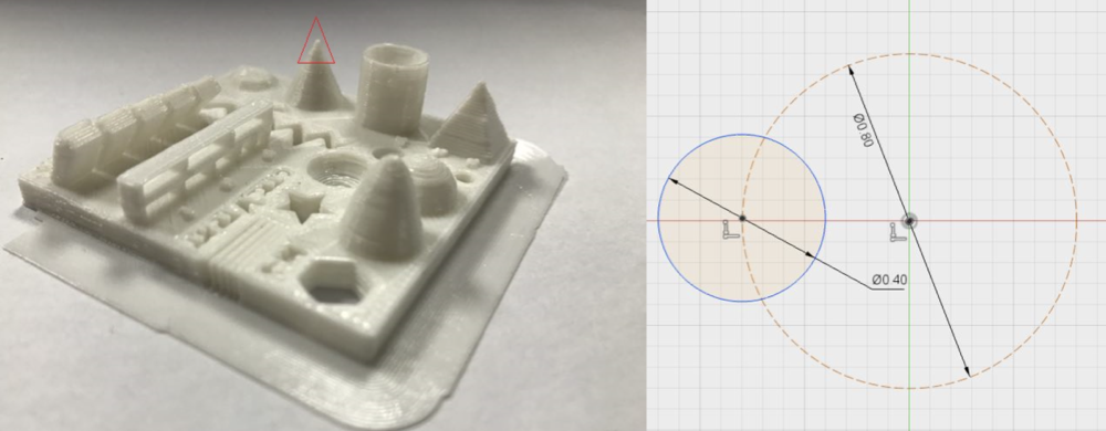 We can find the top of left model is not the same with our design. Then we analysis the machine operation. If we want make a pole, the path of our nozzle is a circle, the diameter at least 0.4mm(in the drawing is 0.8mm ,but we can scale it to 0.4mm), so the smallest diameter of the pole need 0.8mm. If our design small than 0.8 the part would change the shape.
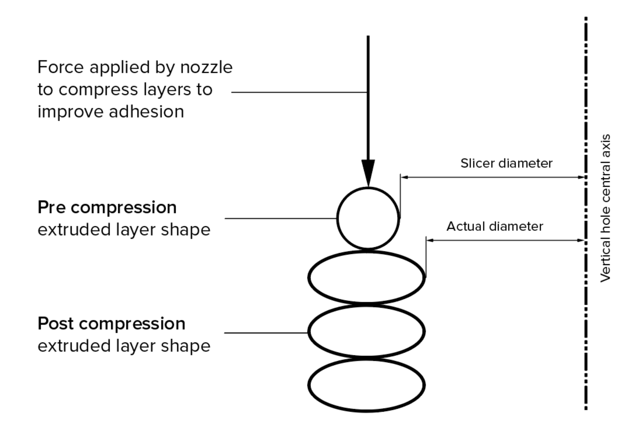
In our design ,we may need vertical axis hole ,but 3D printing size would small than our design.
The picture reference from 3D HUBS
Because of gravity and the compressing force(the material which just output from nozzle is a little soft and easy to change the shape).
The solution is : after printing, we can use drill machine to enlarge the hole to meet our requirement
6 Output data
Most CAD software will give we opportunity a parameter called chord height or tolerance. The chord height is the maximum distance from the surface of the original design and the STL mesh. If we choose the right tolerance, our prints will look smooth and not pixelated. It’s quite obvious that the smaller the chord height, the more accurately the facets represent the actual surface of the model.